Studio 7: Digital Ins and Multiplexed Outs
You can access the repository for this studio here.
Introduction
We’ve explored analog output, analog input, and digital output. Now it’s time to look at digital inputs and more complex LED displays.
Objectives
By the end of this studio, you should know:
- how to read digital inputs,
- how to debounce a mechanical push-button switch,
- how to follow a slightly more sophisticated schematic diagram
- how to light individual LEDs in a multiplexed display.
Push-button inputs
The first thing we’ll do today is explore push-button inputs in more detail. This includes investigating the bouncing properties of the buttons themselves.
Mirror
Complete the sketch called mirror so that it reads the state of the push-button input and sends it to an LED digital output (i.e., flash an LED on when the button is pressed). The program should repeat this operation continuously.
Extend this program to count the number of times the push-button has been pressed. For example, if the button is pressed and released three times it should count to three. You can detect a press either as the input changes from 0 to 1 or as it changes from 1 to 0. Each time the count increases, display the current value of the count in the Serial Monitor.
Does the count always accurately reflect the number of times the button has been pressed?
Debounce
Complete the sketch called debounce so that it reads the state of the push-button using a proper debouncing technique, like the one covered is in this tutorial from Arduino. (This example uses an external resistor as a pull-down. We have been using an internal pull-up, which requires different logic!) In your opinion, does the tutorial use proper delta-time techniques?
Check that your push-button is appropriately debounced by repeating the counting experiment above. What debounce delay is necessary for your push-button to be reliably debounced?
LED-based 5x7 pixel display
In the next assignment you will be asked to display characters on the 5x7 pixel display. In this studio we will start by just lighting individual LEDs in the matrix.
Light an individual LED
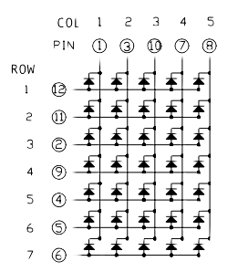
The LED display is organized as 5 columns and 7 rows of pixels (each an individual LED). The combination of 5 columns and 7 rows means we have 35 individual LEDS. Using the LED techniques we’ve covered this far you’d need at least 36 wires to control that many LEDs (35 to control each individual LED’s on/off and one for a ground that is shared by all LEDs), but the device you’ll be using only has 12 connections total. Five of the connections control columns and the remaining seven control a row. LEDs are connected between the rows and columns and an LED will light when its column connection must is at a lower voltage than its row connection.
The hardware we will be using for this studio is the 5 by 7 display manufactured by Liteon. The full datasheet for the display is here, and the pinout is shown in the image below:

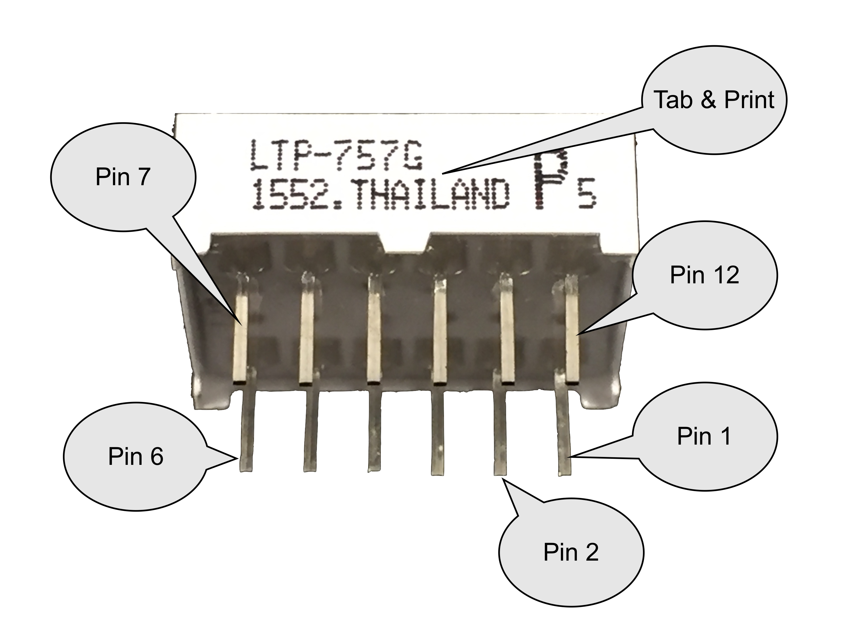
Electronic parts come in many different shapes and sizes. This particular display’s shape is a Dual In-line Package, abbreviated “DIP”. When looking at the bottom of it you can clearly see the two (dual) “lines” of wires used for electrical connections.
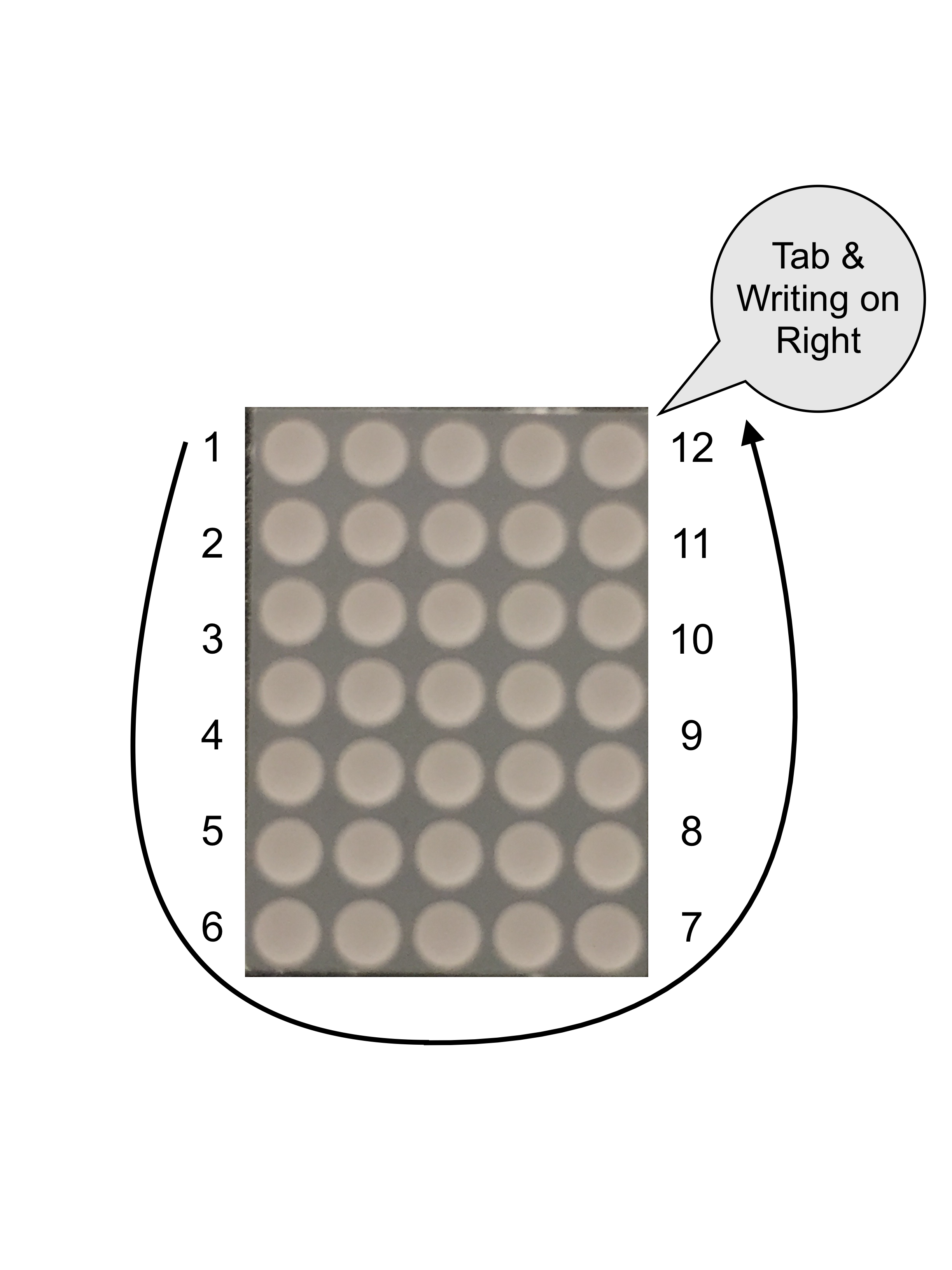
To understand how the pins are numbered, find the side of the 5 by 7 display with text on it and the small tab. “Pin 1” is on the opposite side.

The pins are numbered counter-clockwise starting from Pin 1, like:

Using the pin diagram and datasheet to help you, you’ll need to construct a circuit that connects the rows of the display to digital pins 2 through 8 making sure to include a resistor (>550 Ω1) for each pin. Then, connect the column pins directly to digital pins 9 to 13 (without a resistor). Double check your wiring on this part. You will be using this for the Studio and the Assignment, so it’s important that you get it correct and that you are consistent. Ask a TA or an instructor if you need help.
You should ensure that the other hardware that uses these pins (2 through 13) is disconnected (at least to the extent that you can) and insert the pixel display into the breadboard. Be sure that pixel display’s pin 1, which is marked on the part, is up and to the left. Keep the pins straight as you insert it into the breadboard.
To get an individual LED to light, the digital output associated with its column must have an output LOW and the digital output associated with its row must have an output HIGH. This creates a path from the HIGH output, through the resistor connected to the row, into the row conductor in the display, through the individual LED, to the column conductor in the display, to the LOW output pin. Note that while the pin(s) connected to the rows have an OUTPUT pin mode, the current actually flows into the pin because the output voltage is LOW (which is 0V, or ground). Consequently the 5V will leave the “HIGH” pin for the row, go through the resistor, through a specific row’s LED, and out to the column’s LOW (0V / Ground) pin.
To get multiple LEDs to light in a single column, the column output should be LOW and each row output that is HIGH will light the corresponding LED in that row. Row outputs that are LOW will leave the LED dark.
Write a sketch called sequence that lights LEDs in the following sequence:
- all LEDs off, then
- all LEDs in first column on, then
- a single LED (of your choice) in the first column on, all others off
Spend 1-2 seconds in each state above (delay() based timing is fine here), and then cycle back to the beginning of the sequence.
Notice what happens with the blue LED on the Arduino’s board. Can you explain this?
Counting with different encodings
Now you need to alter your sketch so it will doing some form of “counting”. You will need to implement two different styles of counting:
- First do Binary Encoding
- Then convert it to One-hot encoding Your sketch counts by 1 from 0 to 7 (the count after 7 recycles back to 0). You can either:
- Make your code count automatically, letting the LEDs show each count for 1-2 seconds before moving to the next value (again, either
delay()timing or delta-timing is accetpable) OR - use a push-button press to advance to the next iteration.
Binary encoding
Designate 3 LEDs in the first column of your 5x7 LED display as digits 0 (the least significant digit), 1, and 2 (the most significant digit) of the count, and output the value of the count on these LEDs. A simple way to do this is to use brute force testing of each binary digit. E.g.,
	if (count & B00000001)
		digitalWrite(digitPin[0], ROW_ON);
	else
		digitalWrite(digitPin[0], ROW_OFF);
	if (count & B00000010)
		digitalWrite(digitPin[1], ROW_ON);
	else
		digitalWrite(digitPin[1], ROW_OFF);
	if (count & B00000100)
		digitalWrite(digitPin[2], ROW_ON);
	else
		digitalWrite(digitPin[2], ROW_OFF);
The above, of course, requires appropriate definitions and initializations of the digitPin array and the constants ROW_ON and ROW_OFF.
What would be a better way to accomplish this output? (Hint: It can be done in a single line of code)
One-hot encoding
An alternate method of encoding a value using digital information is called “one-hot” encoding. In this method, only one LED is on and the remaining LEDs are all off.
Designate each of the LEDs in the first column as one of the values 1 through 7 (the value 0 has all LEDs off). Each iteration, ensure that no more than one of the LEDs is on (corresponding to the count) and the others are all off.
Expand your horizons beyond the first column
Now that you can control one column, it’s time to expand to multiple columns. Either:
- Light up all the LEDs on-at-a-time from top-to-bottom and left-to-right with each on for just a short time (1s). For example, the top left should light, then go out and the one below it, etc. until the left column is done. Then the next column would go through the same progression. Or
- Use one push-button to advance the row count and another push-button to advance the column count. (If you allow push-button controlled count-up and count-down, you can effectively move the LED light in all four directions!)
Finish up
- Commit your code and verify in your web browser that it is all there.
- Check out with a TA.
Things that should be present in your repo structure:
debounce/debounce.ino
mirror/mirror.ino
sequence/sequence.ino
Key Concepts
- Digital Input
- vs Analog Input
- Debouncing
- Multiplexing
- Encoding
- Binary
- One-hot
- Encoding
- 5 by 7 Display
- Advanced Diagrams
- Lighting up
- Rows
- Cols
- Individual lights
-
Like the LED, there are limits on how much current each pin of the Arduino can supply (source) and how much it can absorb (sink). The Arduino’s pins can both source and sink 40mA. If we want to drive an entire column of 7 LEDs, the pin connected to that column must not exceed the “sink” limit of 40mA. Consequently each LED should be contributing less than 1/7th of 40mA. Selectiong a >550 Ω resistor will ensure the current limits are met. ↩