II. Blinky: The "Hello World" for Microcontrollers
- Overview
- Goals
- Recommended Preparation
- Part 1: Hardware, Programming Setup, and Console Debugging
- Part 2: Circuits, Ohm’s Law, and Fundamental Circuit Constraints
- Project Parts
- Parts 2: Part Selection
- Assembly
- Going Further
- ACM Curriculum
- Reference
Overview
This guide will walk you through the basic steps needed to program the Photon, to control its built-in blue LED, to wire a new LED, and to make the LEDs blink and change brightness.
Goals
- Introduce microcontroller programming basics
- Introduce or review the fundamental Electrical Engineering principles (voltage, current, and circuit safety)
- Verify your hardware and account setup
- Introduce digital and analog output
Recommended Preparation
- Safety First! The electronics used here are relatively safe, but it’s important to respect electricity.
- Read All About Circuit’s chapter on Safety
- Develop proactive lab habits, including:
- Don’t adjust wiring while a circuit is powered.
- Ask for help when in doubt and have someone review your work before powering a circuit.
- Make sure “exposed connections” can’t contact anything conductive, including protective foam used for shipping electronics, antic-static bags used for shipping electronics, metal cases on laptops, metal tables, etc.
- Electricity is faster than you are and faster than your computer! Don’t connect a circuit if the Photon isn’t configured for it — it could destroy the circuit or the Photon. Always Flash an empty sketch on the Photon before using it for a new project.
- Microcontrollers are one of the most common types of computers. Learn what they are.
- Review the AVR Tutorial’s Microcontrollers Basics and Microcontroller vs Microprocessor Comparison.
- Read Electronics Hub’s Overview of the Difference Between Microprocessor and Microcontroller.
- Review fundamentals of Electronics: Voltage, Current, Resistance, Circuits, and LEDs.
- SparkFun’s Tutorials are a great way to get started. See:
Part 1: Hardware, Programming Setup, and Console Debugging
Project Parts
You will need to get the following parts out of your kit:
- The Photon
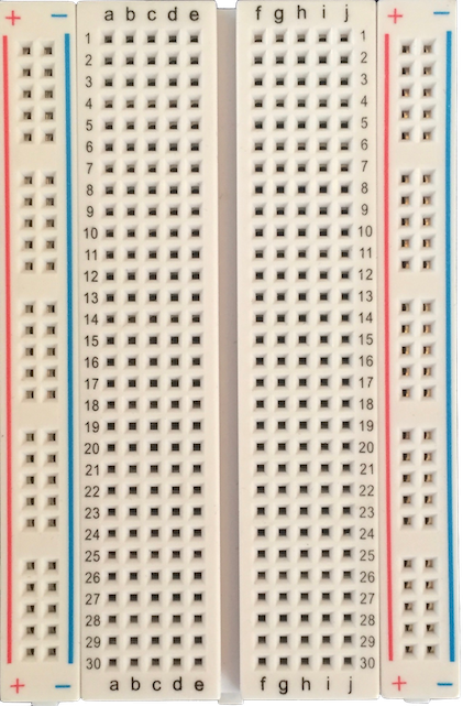
- The Breadboard
- The USB Cable
Assembly
- Remove your Photon from its pack and carefully pull the protective foam off its back.
-
Install your Photon on the breadboard.
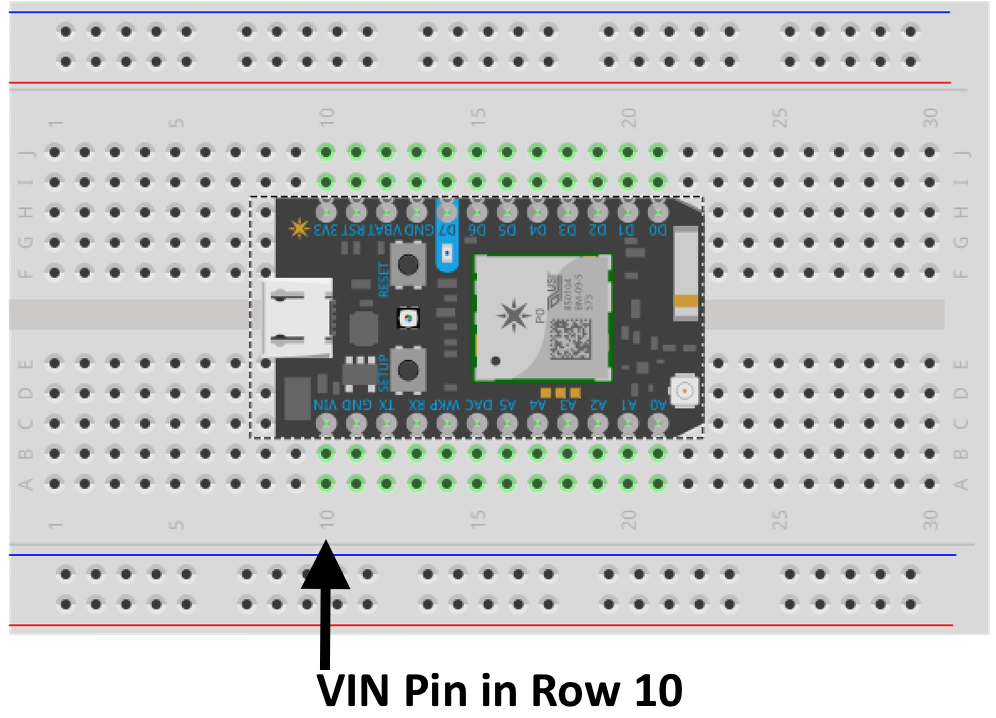
Be sure to push it firmly down so it’s flush with the breadboard.
- Plug the USB cord to both the Photon and your computer.
-
Notice that the Photon’s board has a small blue highlight on the pin marked D7:
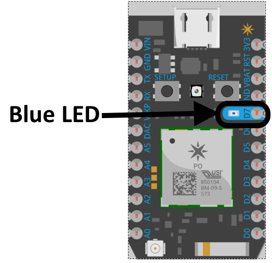
The electronic part in the center of this dot is a Light Emitting Diode, which, as the name implies, can emit light. The following section will program this light to turn on.
Programming
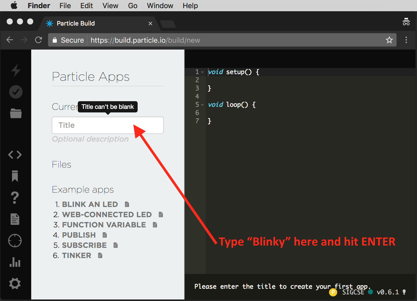
- Open the Particle Web IDE (login with your Particle.io login)
- Enter the name
blinkyfor your program:
-
Type in two lines of code (the panel showing the name of the program may disappear when you enter code):
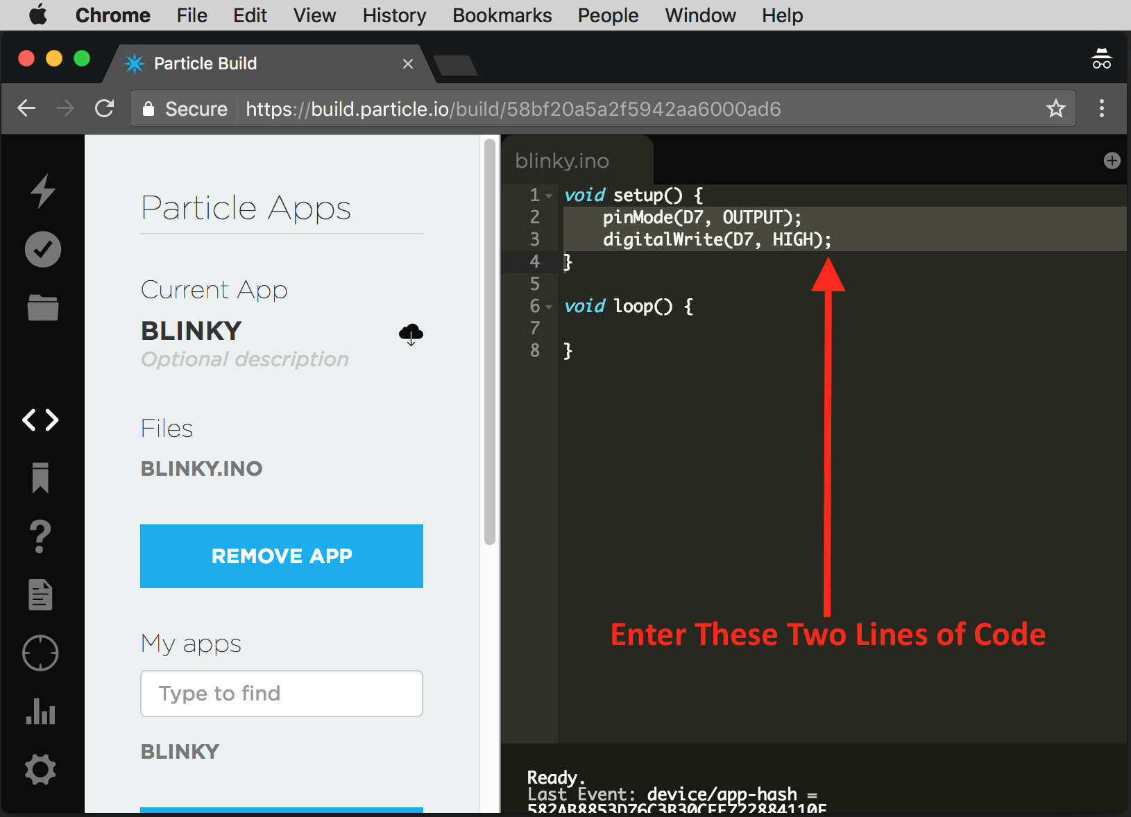
The code is:
pinMode(D7, OUTPUT); digitalWrite(D7, HIGH); - Make sure your Photon is connected to the cloud. It should be “breathing” (pulsing) cyan.
- Click on the “Flash” icon to compile and deploy your code. This could take about a minute:
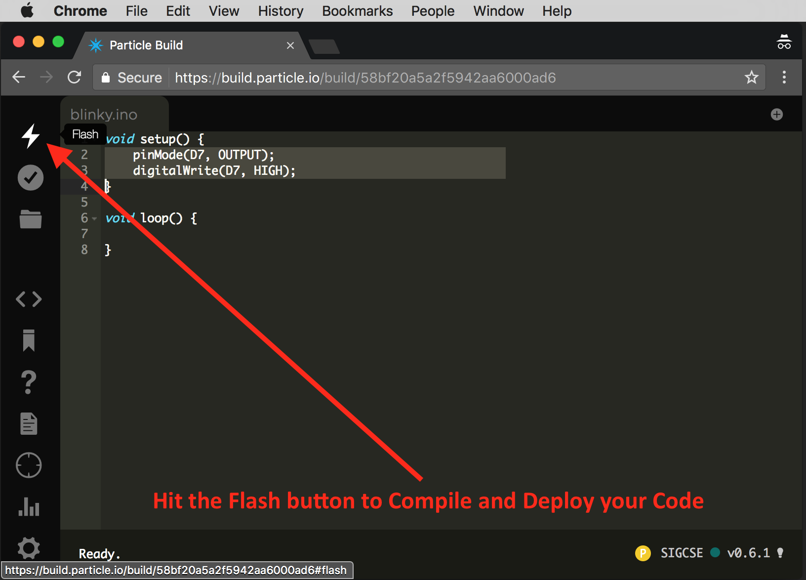
- You should notice that the light comes on. The
setup()function runs once when the program first starts. Typicallysetup()is used to “setup” the Photon by initializing values and configuring hardware. In this case it’s indicating that the pin namedD7is being used as an output and setting the voltage toHIGH(ON) initially, which should turn the light on. - The
loop()function is repeatedly called in a loop. Update the loop to include:digitalWrite(D7, LOW); delay(1000); digitalWrite(D7, HIGH); delay(1000);
Part 2: Circuits, Ohm’s Law, and Fundamental Circuit Constraints
Project Parts
You will need to get the following parts out of your kit:
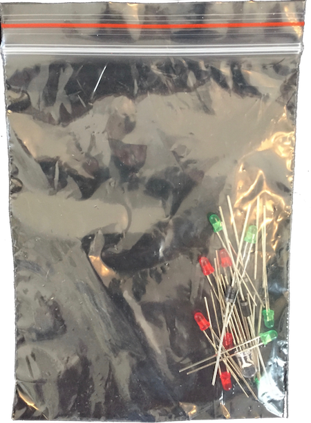
- The pack of semiconductors (LEDs in particular)
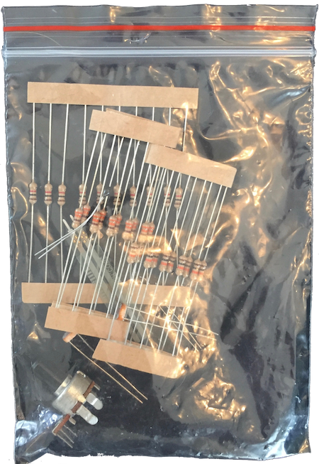
- The pack of Resistive Elements
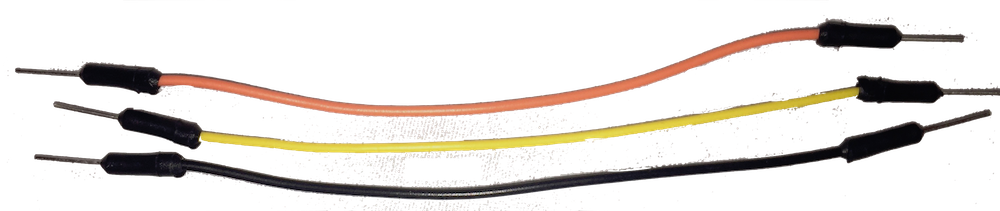
- A few Wires
Parts 2: Part Selection
- Pick either a red or green LED. Based on the data for them:
- They both drop the voltage by more than 1.8V
- They both have a maximum current of 20mA
- They both have a recommended current of 16-18mA
-
Pick a resistor.
There are several constraints that dictate the amount of resistance that should be used with an LED connected to a microcontroller. If there’s too much resistance the LED won’t light (or will be very dim). A small resistance (or no resistance) will cause more current to flow than a high resistance and too much current could:
- Damage the LED. As mentioned, these LEDs shouldn’t conduct more than 20mA.
- Damage the Photon. The Photon has two limitations:
- The Input/Output current max of 25mA
- The Input/Output current total of 120mA. (That is, the total amount of current available across all outputs)
Your kit comes with three values of resistor: 330, 1K (i.e., 1,000 ), and 10K (i.e., 10,000)
Questions
The Photon’s Output Voltage is 3.3V and the LED will reduce this by 1.8V (or more), leaving a 1.5V potential across the resistor. Use Ohm’s law to answer the following questions:- What will the current be if a very low resistance (i.e., 1 ) is used? Does this exceed the limits of the LED or the Photon?
- What will the current be for each of the provided resistance values (330, 1K, and 10K)?
- Which value is the best choice here and why? (Why is one value preferable to the others?)
- The Photon has seven digital outputs. Assuming that all seven will be used for LEDs and all should be supplied equal current, what’s the minimum resistance that would be safe for both the Photon and the LEDs assuming you can use any resistance value?
- Repeat the previous question assuming that you can only use commonly available resistors from this kit.
Use the resistor color code to pick the proper resistance.
Assembly
-
Unplug the Photon before changing the circuit
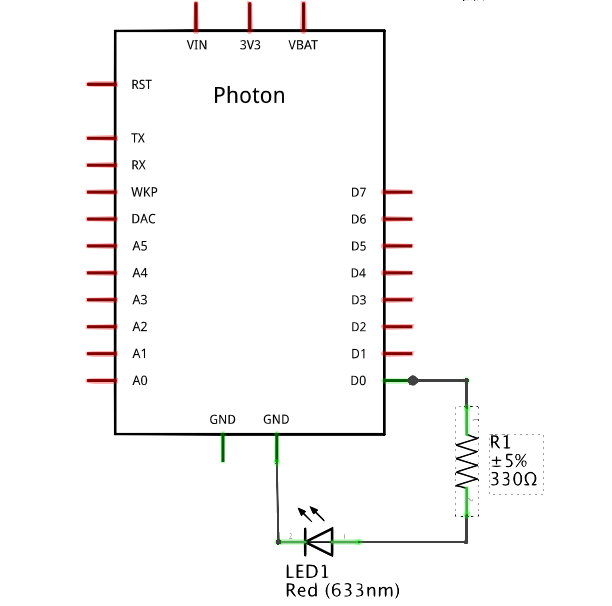
- Construct a complete circuit using the breadboard. The current should:
- Leave a Digital Output Pin, like
D0, - Go through a resistor (with the value selected above)
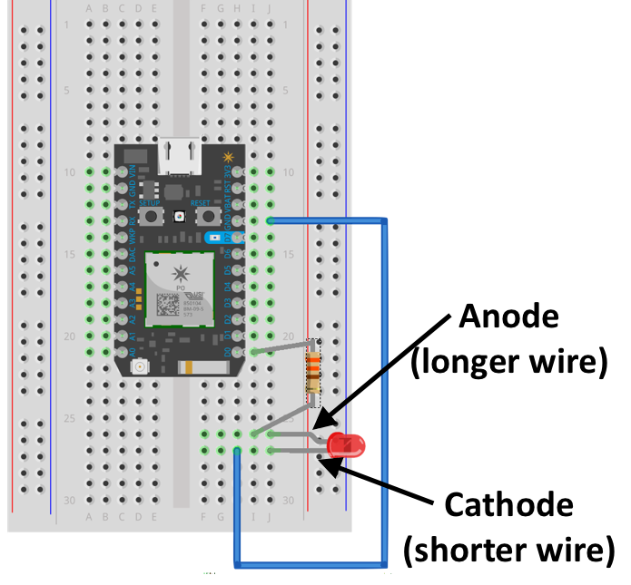
- Go into the Anode of the LED (the longer wire)
- Go out the Cathode of the LED (the shorter wire)
- Return to one of the grounds (
GND) of the Photon
The Schematic view is:
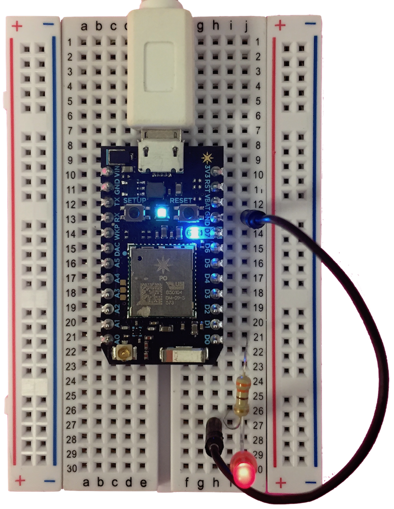
The Breadboard may be wired like this:
- Leave a Digital Output Pin, like
- Now plug it back in and update the program to turn on newly added LED. It should look like this:
Going Further
- Try to make one of the LEDs blink an SOS pattern (…—…).
- Use
analogWrite()to control the brightness of the LED.- Use a
for-loop in conjunction withdelay()to try to reproduce the “breathing” pattern of the main LED.
- Use a
- Explore the other digital and analog output parts in your kit:
Your kit of parts also includes:
- A Tri-color LED, which is just three LEDs in one single package.
- A Piezo Speaker to make
tone()s - A Servo Motor. See the Servo Gong Tutorial!
ACM Curriculum
- The Particle Photon’s IDE and Library are an example of Platform-Based Development.