TODO SLIDES
All posts by bsiever
Micro:bit, MakeCode, & Extensions
Micro:bit
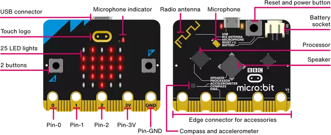
Over the past five years I’ve been an active developer for and user of the micro:bit, a low-cost platform designed by a non-profit organization (and partners) with the goal to “Inspire every child to create their best digital future.”
I use the micro:bit for summer camp activities and have worked on supporting some K-12 modules. Most of my activities are geared towards novices, who benefit from block-based visual programming languages.
MakeCode
MakeCode, developed by Microsoft, is web based development environment that supports a block-based visual programming language. MakeCode supports a variety of platforms, including the micro:bit.
& Extensions
One of the great features of MakeCode is the ability for people in the user community to create “Extensions”. Extensions allow developers to create new sets of blocks that others can use. This allows the platform to grow beyond the originally expected uses and beyond the limited ability of individual companies/organizations to meet all of requests from micro:bit users.
I originally created an extension to support curricular development. Washington University’s Institute for School Partnership (ISP) wanted to pilot test some new modules for their mySci curriculum (used in over 200 schools). The ISP was willing to share the curricular materials that resulted from our collaboration, which can be found here. And here’s a video of it in use:
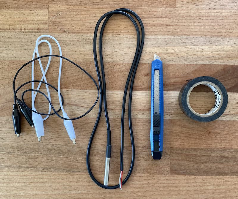
My part in this was developing the support for an appropriate temperature sensor. I chose to use the Dallas Semiconductors (now Analog) DS18B20. One of the first problems we encountered in early testing was inconsistent temperature readings! A little research led to Chris Petrich’s great resource for counterfeit DS18B20s. Afterward, we started using DS18B20s from authorized resellers (YourDuino.com, which was sold) and the inaccuracy problems disappeared. Although I haven’t tried them, I expect the AdaFruit sensor/resistor combo to be a great choice: https://www.adafruit.com/product/381.
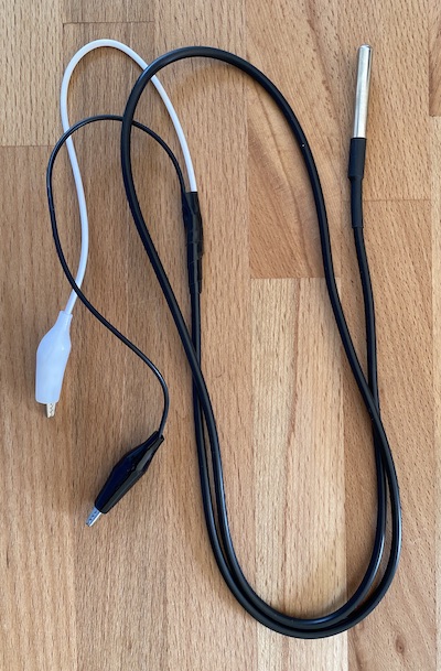
I created a MakeCode block specifically for the DS18B20 to make it really easy to collect accurate temperatures. My original version required connecting three wires and a resistor, but I created a second version that can work with just two connection. Both version were added to the list of official “MakeCode Extensions”:
- The documentation for the original version, DSTemp, is available on the MakeCode site (or at my GitHub repo).
- The documentation for the 2-wire version, DSTemp-2wire, is also available on the MakeCode site (or at my GitHub repo). It includes step-by-step instructions to “make” the sensor (i.e., how to wire it).
Extensive Extensions
My work to support the ISP was a great introduction to the micro:bit MakeCode ecosystem. I’ve gone on to develop several other Extensions with varying degrees of complexity. There are a variety of things about MakeCode development that are a good fit for me:
- Creating blocks for novices requires careful thought about semantics and novice programmers.
- Extensions require a variety of low-level concepts, like memory management, embedded systems concepts, operating systems concepts, etc.
- C++ is used at the hardware level, but TypeScript is used for most of the API level that is exposed for MakeCode users. The mix of the two requires a variety of programming skills.
- The scope of the MakeCode extensions is modest and can fit my schedule.
- Due to prior industry-focused projects for consumer electronics, I had already worked with the processor line used in the micro:bit (Nordic Semiconductor’s nRF51 and nRF52) before the micro:bit was released. Since the prior work was focused on Bluetooth Low Energy “gadgets”, I already had a deep knowledge of some aspects of the micro:bit hardware, which has been beneficial for my micro:bit work.
I’ve continued to develop extensions that extend the micro:bit in a variety of ways.
My Extensions
DSTemp & DSTemp-2wire
DSTemp official page (or at my GitHub repo)
DSTemp 2-wire officia page (or at my GitHub repo)
As detailed above, these are the two that started my journey into micro:bit MakeCode extensions.
BLE HID
Official page (my GitHub repo)
BLE stands for Bluetooth Low Energy (which the micro:bit’s radio can do) and HID stands for Human Interface Device. This extension allows the micro:bit to act like a programmable bluetooth keyboard, mouse, media controller, game pad, or a combination of them. Here’s a brief demo of some of the ways it can be used:
This extension was originally created in response to a request on a MakeCode forum: “Steering Wheel with McroBit?” [sic], where a micro:bit user wanted to know if they could use their micro:bit as a steering wheel controller. Since I had been working with Bluetooth Low Energy on the Nordic platform long before the micro:bit, my reaction was “Why not???”. The desire / value of this sort of support came up among users, members of the Microbit Education Foundation team, and members of the Microsoft team, such as here and here. Those posts were before the release of the second version of the micro:bit, which was much better suited to supporting this sort of feature due to a combination of additional memory, a better Bluetooth interface, and a faster processor. Of course, it still took moderate effort to make this sort of support available to MakeCode users and reasonably easy to use.
This is my most elaborate extension so far. It required substantial “reengineering” of the underlying runtime (i.e., some mild hacks to do things that were not well supported). This is also one of the one’s I’m the most proud of, but not because of the tech skills involved in creating it…because of the potential uses.
Soon after releasing the initial version of it, it was already being explored as a tool to prototype and create low-cost assistive technology. Thanks to Loreto Dumitrescu, who put together a workshop to share this work! The slides from the workshop can be found here — they include a full walk-through of the concepts and creating/configuring an assistive device. Loreto’s build instructions for a hand-based switch can be found here. And build instructions for my minor variation, which uses a foot based switch, can be found here.
Recently PrintLab developed a 3D Model of a fantastic case to support switch access. They put together a great video:
Loreto organized a workshop discussing the Tap and Assistive Tech. She’s put together a post with the full workshop video and links to all the resources, including the printable/modifiable models: “Empowering Accessibility: Using Micro:bit and 3D Design as a Switch Interface“. (Kudos to Loreto — and thanks to her for including me in the effort!)
Time & Date
Official page (my GitHub repo)
For several years I helped with summer camp activities that created wearables based on the MakeCode Watch example. These are really great activities: Minimal and cheap materials, easy to assemble, neither too time consuming nor too short, and kids can express their style/personality. The downside was the micro:bit didn’t have blocks to represent “wall-clock time”. And the process of actually showing time by counting seconds was too complex for a novice-friendly camp activity.
In addition to the watch activity, I realized that my continuing interest in data logging and science activities could really benefit from wall-clock time (without the expense of an external hardware real-time clock module). Consequently, I created a set of blocks to support a software based real-time clock. There are definitely some limitations, like losing the time on reset and being dependent on modest clock accuracy of the micro:bit (v1 is pretty good, but v2 can drift by ~4-5 seconds per day).
This extension was a lot of fun to think about. It required both careful consideration of the semantics of representing and interacting with wall-clock time as well as understanding the underlying microprocessor clock facilities.
Button Clicks
Official page (my GitHub repo)
An educator using the micro:bit wanted the ability to detect double clicks and was having trouble coming up with a suitable solution (they solicited ideas via the micro:bit developer Slack).
Since the micro:bit just has two buttons, detecting different types of clicks can substantially improve the ability to interact with it. I wanted the ability to distinguish single clicks, double clicks, and long presses (holds) to support my BLE HID extension. Specifically, I wanted to be able to quickly create media remote controls. For example, I wanted a single click of Button A to be play/pause. A single click of Button B to be next track. A double click of Button A to be volume down; A double click of Button B to be volume up. And holding Button A would be rewind while holding Button B would be fast forward.
Detecting different types of clicks requires tracking the timing of events (when a button is pressed and released, how long it has been since it was released, etc.). A lot of the subtle details of click detection are well-explored in the embedded systems community, especially for consumer electronics, but are not well known to the typical micro:bit audience. Although there is benefit in end users trying to replicate the double-click detection on their own, it seemed like: a) the limited buttons were an impediment to some users’ ability to create things and b) the knowledge needed to support click detection was beyond what could reasonably be expected of many micro:bit users…. so I created a library to simplify the process that’s sufficient for many needs.
(Display) Rotate
Official page (my GitHub repo)
I’ve heard that some K-12 educators want to show how accelerometers are used in cell phones to control the display orientation. Although the micro:bit has some support for rotating its display, this was not well supported in MakeCode. This extension (with the help of updates from the Microbit Education Foundation team — Thanks Martin!) provides a block to change the display orientation and create satisfying examples that rotate dynamically in response to the orientation of the micro:bit.
Air Quality: SEN55
SEN55 official page (or at my GitHub repo)
I was searching for an interesting source of data for my data logging projects as well as a sensor that could help me learn a bit more about PCB manufacturing (specifically, testing JLCPCB’s PCB Assembly — I plan to release the board design as open source too. It’s relatively cheap to manufacture). The Sensirion SEN55 seems like a good fit:
- It provides the type of data that should be collected over a long term.
- It provides multiple types of data: Temperature, Relative Humidity, Particle Mass Concentrations, and data on Volatile and Oxidizing gases.
- It’s got a really simple (I2C) interface, but still has some interfacing challenges (requires 5V power and I2C isn’t accessible via the ring connectors).
BLE Log Access
Pending review for official extension (or at my GitHub repo)
My current work is again focused on data logging applications. The newest version of the micro:bit (v2) includes support for a “data logger“. The data logger blocks allow the micro:bit to accumulate data from long-running experiments/projects, like tracking the temperature in a stream over a week or the sunlight in a school classroom over a few days. It stores the data on the micro:bit. In order to retrieve the data, the micro:bit needs to be connected to a computer. When connected, the micro:bit shows up as a USB drive and users retrieve the data by opening a file on the drive.
Data logging greatly extends the ability of the micro:bit for a lot of STEM applications, but removing it and connecting it to a computer to retrieve the data could be a hinderance for some applications.
My current work is two parts:
- A new set of blocks (just one block actually). The current version of the work can be added by using this URL for the extension: https://github.com/bsiever/microbit-pxt-blelog . The block will make the micro:bit appear as a Bluetooth device. (Currently this only works with the beta version of MakeCode: here)
- A corresponding set of libraries to retrieve the data. So far, I have created a Web Bluetooth library (here: https://github.com/bsiever/microbit-webblelog). This will allow applications to retrieve the data over Bluetooth. The example includes a simple webpage to retrieve the data and save it as a CSV file (here).
This approach allows longer running data collection, live viewing of data in long running tasks, and deeper “embedding” of the micro:bit. It also has better association of the data with “wall-clock time”, which is really important for many long running data collection tasks. For example, temperature-based work is often strongly influenced by the time of day. Having a clear association between the time of day and each data sample can be helpful.
Longer term plans include development of a mobile app to retrieve/graph the data (Flutter!?!).
Update: Graphing Site!
- A senior project team at Michigan Tech developed a web-App that collects and graphs data (works on Android Devices:
- The deployed app is at https://2024-ui-sp.github.io/Micro-bit-ble/ .
- Source code at https://github.com/2024-UI-SP/Micro-bit-ble/ .
- Thanks to Isaac Elebnbaas, Parker Kirwin, Jack Snowden, Ben Walby, Jacob Smith, Josh Staples, Jordan Bramer, AK Syracuse, Sidney Gillig, Will Sisson and Professor Pastel!
Morse Code
Morse official page (or at my GitHub repo)
Thanks to work from others and the possible combination of Morse Code with my BLE HID extension, I decided to try creating an extension that supports keying in, encoding, and decoding Morse code. It also works well with the button press/release semantics provided by the Button Clicks extension described above.
Loreto has developed a great example “two button keyboard”, which can be used as assistive tech for those who are unable to use a regular keyboard. It combined 3D printing, the Morse Code extension and the BLE HID extension. The build details can be found here: Microbit: 2 Button Morse Typewriter.
Flash Storage Access
Not an official extension (my GitHub repo)
In response to a MakeCode Forum post from @mwest226, I created a prototype extension that provides users with access to Flash-based storage with get/put operations that store key/value pairs (strings only). @mwest226 also pointed out memory leaks in my work — thanks!
If there’s sufficient interest I may clean this up and submit it as an official extension, but MWest’s fork may be a better candidate for an official extension!
i2c Pins
Not an official extension (my GitHub repo)
This extension allows the pins used for i2c communication to be redirected. This is especially valuable in some hardware devices that connect to the board via the “holes” (or even alligator clips), which are not the default locations for i2c signals. The Python APIs provided the ability to redirect i2c pins, but MakeCode did not — some accessory developers needed this ability for accessories that did not use an edge connector. (Thanks to MakeKit for inspiring/sponsoring/testing this work)
This is not approved as an official extension because it may have side effects that are not obvious to end users, especially with the V1 micro:bit where it will disable use of the built in accelerometer. None the less, it is stable and there are products that rely on it. Products can include it as a dependency in their custom blocks so end users are not bothered with adding an unofficial extension.
Related (not an Extension)
My GitHub repo
In order to support projects that interact with the micro:bit, I’ve created a WebUSB library that lets simple webpages connect to the micro:bit (over USB) and interact with it via serial communication. Several projects (and at least one company) have adopted this library. After recent changes in the interface chip on the micro:bit v2.2, which changed USB enumeration slightly, I migrated this to be a user-friendly wrapper around DAP.js.
SIGCSE 2021: Game On! Inspired CS Education with MakeCode Arcade
Workshop Slides
Bringing Computation to Life: Data, Sensors, Data Collection (Streaming & Logging)
Micro:bit: A classroom-friendly tool for sensors and data collection (MST Regional STEM Conference 2023)
micro:bit Live: A sprint through graphing & data collection
- PDF Slides
- iCloud/Keynote presentation
NJ CSTA: Programming the Micro:bit with Python
Micro:bit: Graphing & Visualization
Quick intro of misc. work in Graphing and Visualization to Micro:bit Champions cohort
2020 CCSC Midwest Conf Workshop: Micro:bit Magic
Workshop Slides
Slides (notes format with full builds)
Videos
- Streaming accelerometer data to the browser over bluetooth: https://youtu.be/eJiddQwKPck
- Using the micro:bit to control a servo from the micro:bit phone app: https://youtu.be/UuGTBZRwC-8 (Includes a link to the Bitty Controller, an Android alternative to the iOS app)
Pre-workshop Prep
- Please use a recent version of Google Chrome for all Workshop activities.
- Many activities can be tested in a web browser but are more satisfying with hardware. Options for buying hardware are below. Note that:
- Micro:bits come with a USB Type-A cable. If you have a machine with only USB-C, be sure you have an adapter (For example: Amazon).
- One activity will demonstrate micro:bit to micro:bit radio communication, which can be done in the simulator or with two real micro:bits. I recommend getting two micro:bits, but it’s a small component of the workshop.
Purchasing hardware
You can either purchase a complete kit from me or buy parts individually:
- To purchase a complete kit from me:
- Please request a kit by Sept. 15th
- Kits will be shipped approximately one week before the workshop (by Sept 18th).
- I buy in quantity and/or at a discount from a local store, so kits may be cheaper than buying all parts individually.
- Payment may be made by PayPal, Venmo, CashApp, or sending a personal check. Contact me at: bsiever@gmail.com for details.
- There are two options:
- Kit with 1 micro:bit Go and one set of clips/sensor/headphones (sufficient for about 90% of the workshop activities): $30
- Kit with 2 micro:bit Gos and one set of clips/sensor/headphones: $45
- To purchase items individually from Amazon:
- Get one or two Micro:bit Go kits: Amazon
- Two alligator clips: Amazon (this is a pack of 10, but only two are needed)
- Headphones or earbuds with phono connector (it’s likely that you already have some): Amazon
- (Optional temperature/humidity sensor): BOTH:
- DHT-11 sensor: Amazon Sensor 5 pack
- 3 alligator-to-male pin cables: Amazon Cables (10 male-ended, 10 female-ended)